
CSC 103
How Computers Work
Smith Computer Science
How Computers Work
Smith Computer Science
recall that we can represent a logical process based on inputs as
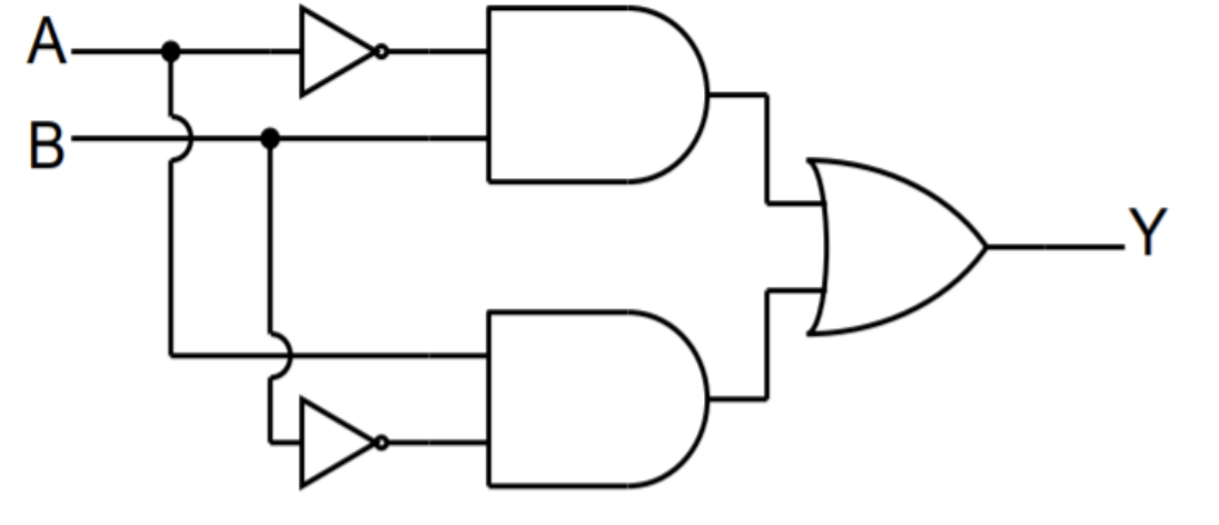

We can combine basic gates to construct more complex circuits that complete more complex operations.
The trick is to combine these to produce operations that are useful to us.
We are already capable of producing logical operations from simble bit-to-bit inputs.
Now, we'll try to use logic to produce arithmetic operations
As we've seen before, we can add two binary numbers one bit at a time and obtain a result:
\[
\begin{aligned}
\texttt{carry:}\mathit{1011} \texttt{ }&\\
\texttt{A: } 1011&\\
+ \texttt{ B: } 1001& \\
\hline
\texttt{Out: }10100&
\end{aligned}
\]
For clarity, I've removed the "0b" from each number. they are all binary, though.
As seen above, we can use the typical arithmetic rules only on base 2.
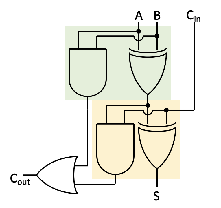
We can add two bits together (one bit a from A, and one bit b from B) using the following rules:
| a | b | Carry | Out |
|---|---|---|---|
| 0 | 0 | 0 | 0 |
| 0 | 1 | 0 | 1 |
| 1 | 0 | 0 | 1 |
| 1 | 1 | 1 | 0 |

| Carry-in | a | b | Carry-out | Out |
|---|---|---|---|---|
| 0 | 0 | 0 | 0 | 0 |
| 0 | 0 | 1 | 0 | 1 |
| 0 | 1 | 0 | 0 | 1 |
| 0 | 1 | 1 | 1 | 0 |
| 1 | 0 | 0 | 0 | 1 |
| 1 | 0 | 1 | 1 | 0 |
| 1 | 1 | 0 | 1 | 0 |
| 1 | 1 | 1 | 1 | 1 |
Let's do it using the usual steps:
Obtaining a result for the addition of two multi-bit numbers is the result of linking a sequence of full-adders:
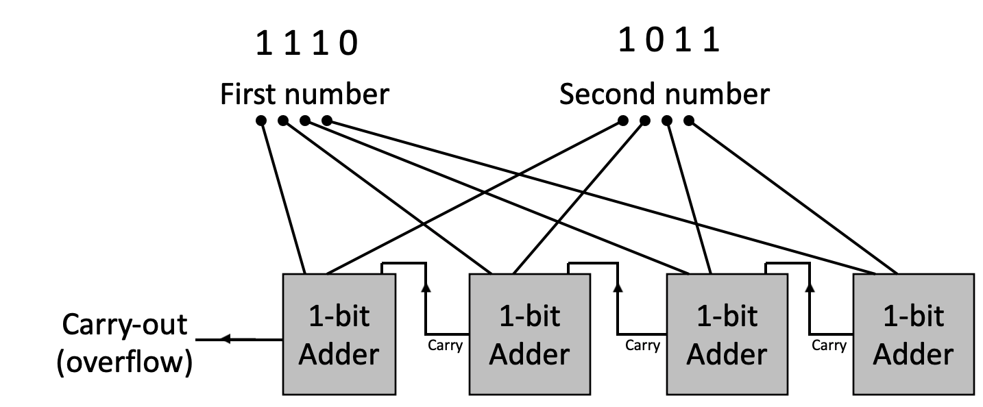
Note that the Least Significant Bit (LSB) is on the right and the Most Significant Bit (MSB) is on the left.
Activity 4 :[2 minutes] : Let's build a 2-bit Full-Adder:

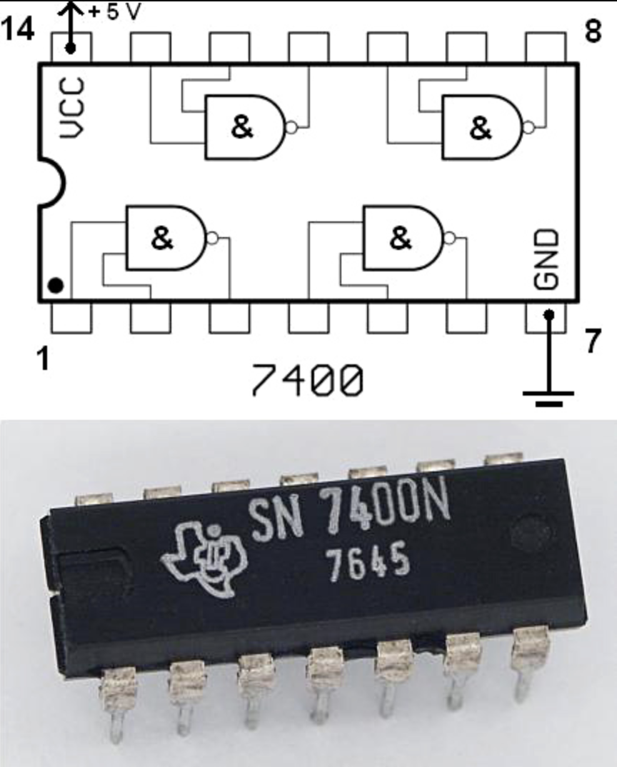
There are small components that contain the classic logic gates: AND, XOR, NOT, etc.
They are called Integrated Circuits (IC) and are usually called "Chips".
Some of the most sed ones are for Prototyping: which is when you build "test" circuits which are larguer and slower (but easier to build and test) than the final product.
You can simply connect these to a power source and to some inputs, and link them together using wires to replicate the circuits we discussed above.
These are sold in "groups" and look like this (diagram on top, chip on bottom):
Important dates (To be added to Moodle and class schedule soon)
Please fill this out before leaving:
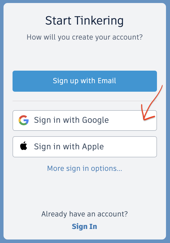
IF you'd like, you can join Tinkercad for free:
If you have a Google account, you can simply login using your Google credentials (preferred).
Exercise:
Also, if you log out and need to find the tutorials, you an use this link:
Circuits Tutorials
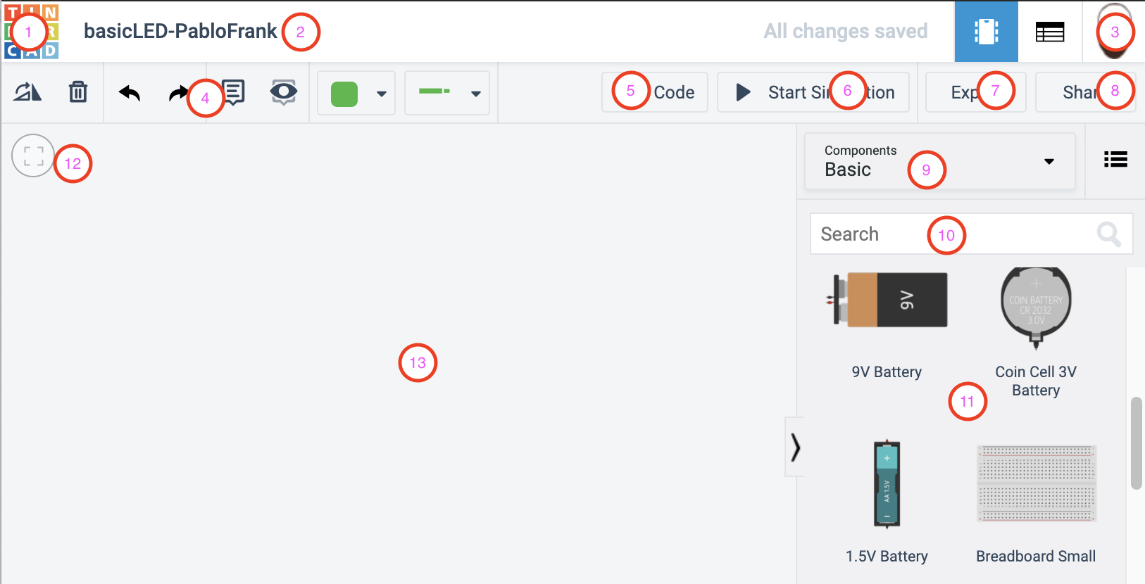
This will open the Circuit Designer.
The following are the main important elements
(THIS IS OPTIONAL!)
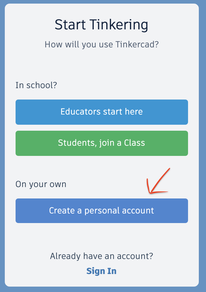
Creating a TinkerCad account
Go to tinkercad.com/join and create a free account.
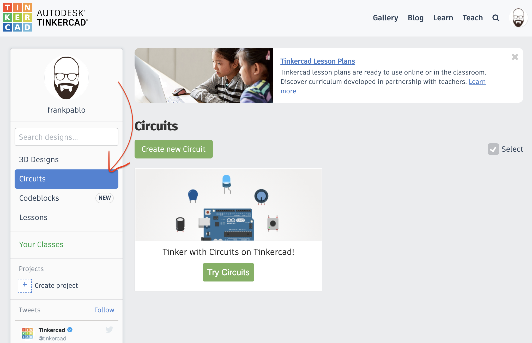
The TinkerCad Dashboard
The following is what you should see in your TinkerCad Dashboard.
Note that you should select the Circuits tab on the left in order to see your circuits (see the arrow).
To start with, you'll have no circuits but you will have a small tutorial to teach you how to use the interface.
The TinkerCad tutorials
Now, let's complete a series of tutorials to learn to use TinkerCad Circuits.
Start the tutorials by pressing Try Circuits. Once each tutorial is completed, you can continue to the next one by pressing the continue button that will appear.
Complete the following tutorials:
You can always go back to your dashboard by pressing the TinkerCad logo:

The Circuit Designer
As a final exercise in this Lab, let's perform a calculation, select the right components, and we'll build a simple circuit using wires, a breadboard, a battery , a resistor, and an LED.
First, go to your circuits dashboard an press the Create new Circuit button.

Once you've joined, follow this link: AND-XOR