Lecture Notes 04: Logic Gates
Outline
This class we'll discuss:
- Recap: Boolean logic and functions
- Recap: Water Analogy
- The Diode
- The Transistor
- Circuit symbols
- Integrated Circuits
- Building the basic gates
- Working with logic gates
- Simulating a Circuit
- Final Project: possible themes
 For now, we're looking at the "what?" not the "how?"
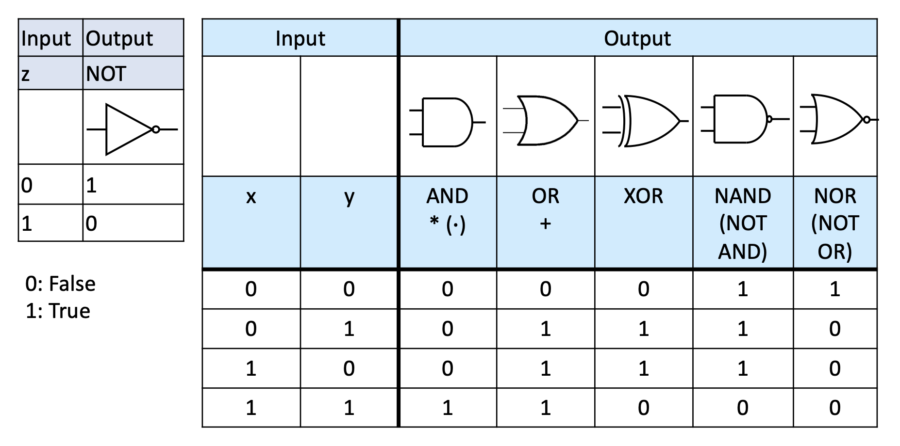
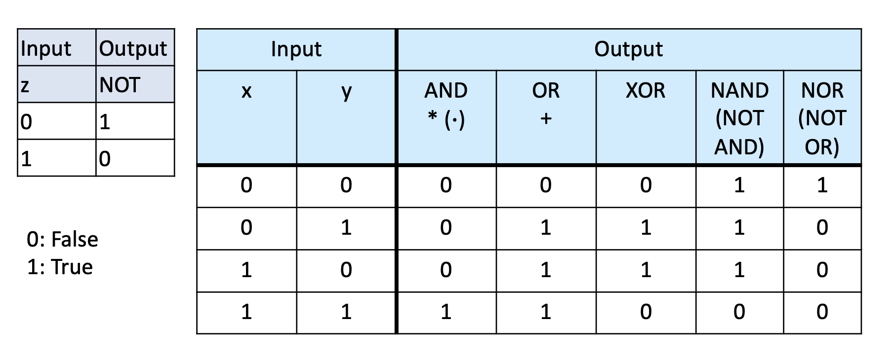
Recap: Boolean Logic
recall that we can combine logical operators to obtain a truth value output:
Now, we want to convert this logic that uses truth values into circuits that use electrical signlas.
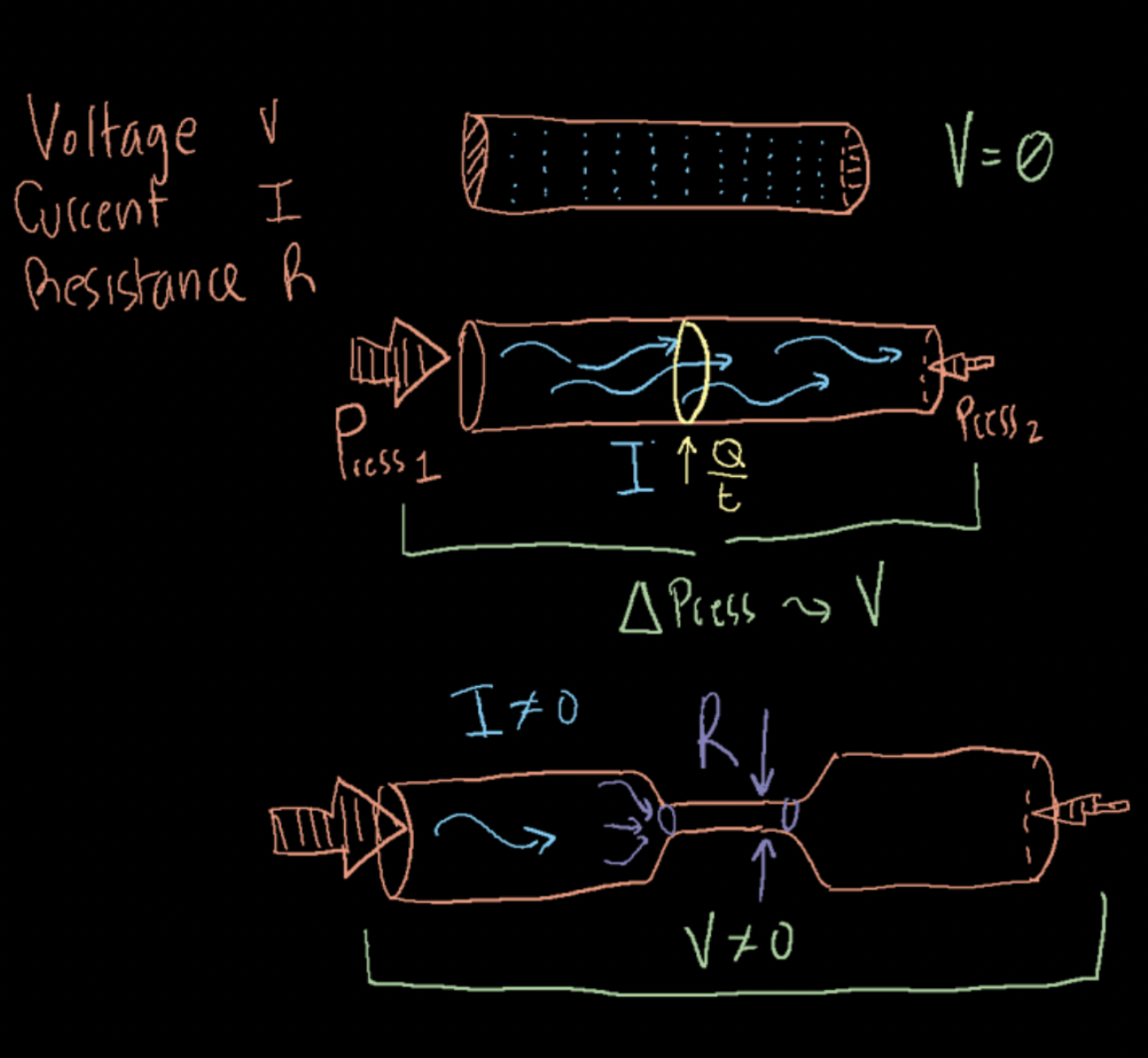
Recap: The Water Analogy
recall that we can use water to build intuition about how circuits and signals work
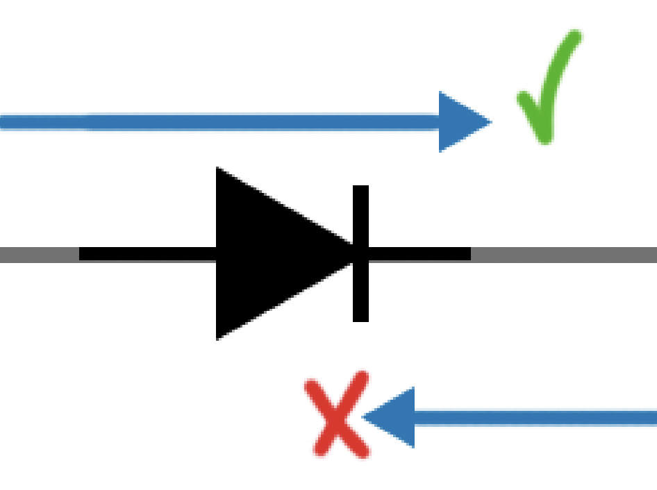
The Diode
The diode is an electric component that acts like a "one way valve" but for current, instead of water.
The symbol for a diode is like an arrow with a barrier (current can onl pass in the direction of the arrow):
The Transistor
A transistor is an electronics component that lets electricity pass through from one of its input pins (collector) to one of its output pins (emitter) if there is an input on the third signal pin (base).
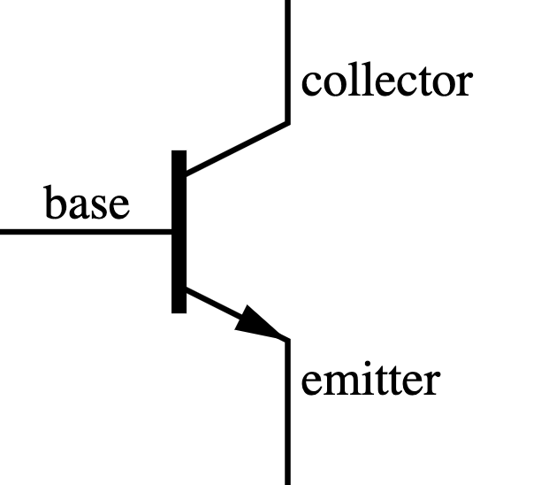
The brilliance here is that this allows an electric signal (that can be programmed) to control another electric signal; making the electric component capable of self-guidance.
The transistor works like that:
- if there is no signal into the base, then current does not flow from collector to emitter;
- if there IS a signal into the base, then current flows from the collector into the emitter (and one can use that current to do other things);
The following is an animation of a simplified transistor:
Check an
animation that explains how a transistor works by using the water analogy.
One of the main uses of a transistor is as a
switch, where some signal allows the passage of current to another part of the circuit.
However, the signal can be a low-voltage (low current) one and it might allow the passage of a HIGH-voltage (high-current) one.
Because of this, transistors can also be used as
Amplifiers:
We can join several of these transistors in different ways to create circuits that reproduce logic operations on input variables (signals).
Combining transistors to generate logic
Given the way transistors work, and using the simplified operation shown above,
Activity 1 :[2 minutes] : Analyze this diagram and discover the behavior of the circuit:
- How should we analyze it?
- What does this resemble in Boolean Logic?
Logic Gates
A logic gate is a digital circuit that behaves like its boolean operator counterpart.
The Boolean Operations and the Logic gates are shown in the tables below:
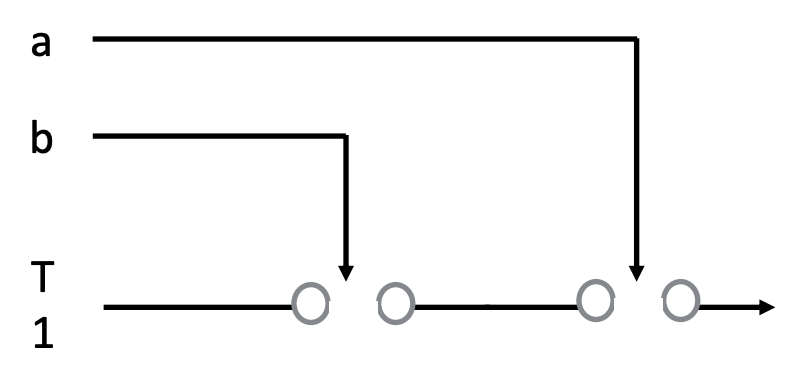
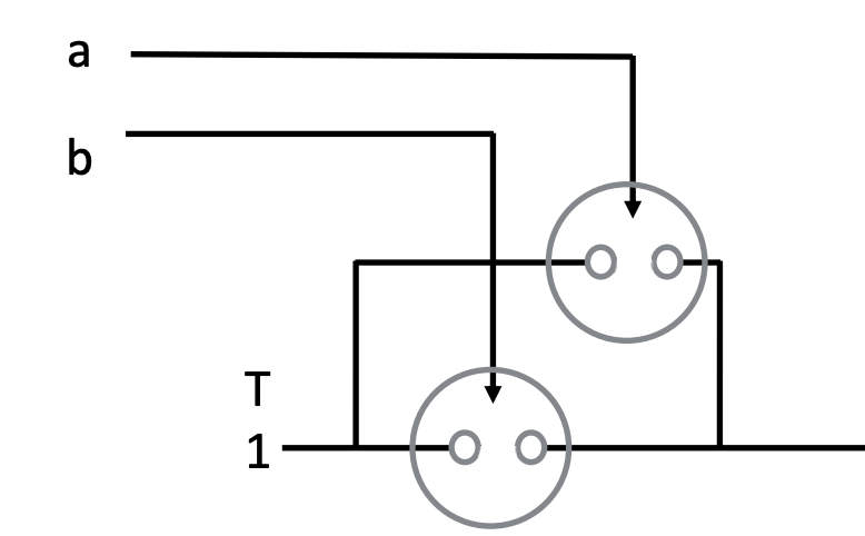
Let's see one simplified view of a gate in and how the transistors help the logic:
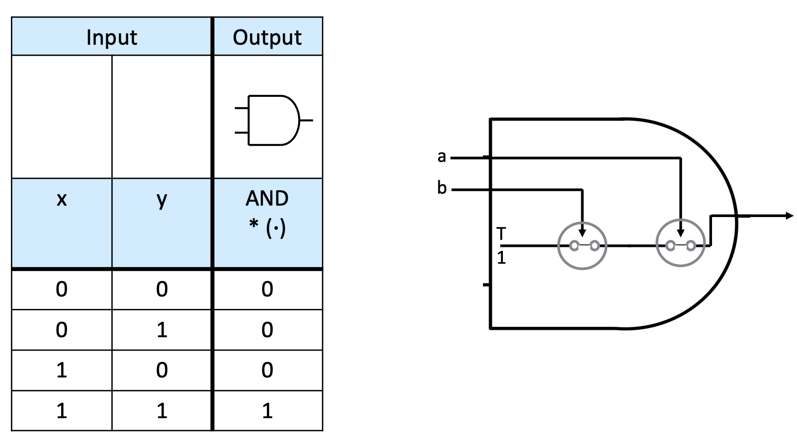
The transistors act as switches that can let current flow through or not.
In this case, the two inputs (a and b) are used to activate the switches (into the
base of the transistor) to allow the passage of a default
True (current).
Note that
only if both
a and
b are
1 does the output of the gate result in
1.
In the water analogy, it is like a pipe with a reservoir in one side and two valves in series.
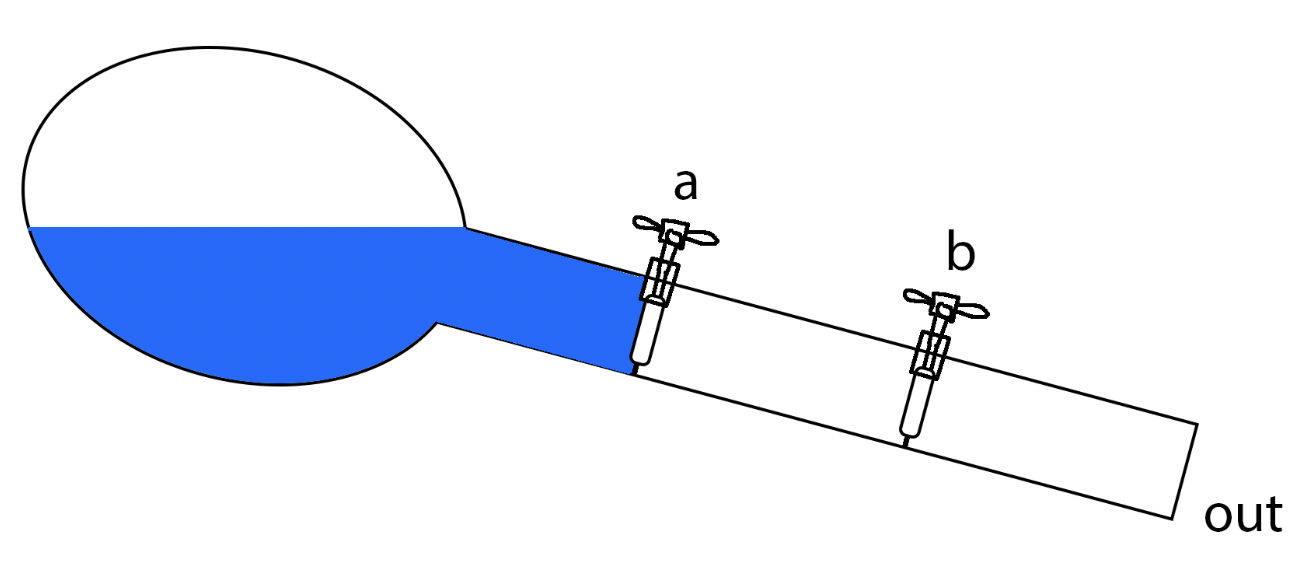
Either both valves are open or no water flows.
Note that in this example, instead of water pressure, we are using gravity. I have added this example in case you see it somewhere else in the literature or on the web.
Activity 2 :[2 minutes] : Analyze this diagram and discover the behavior of the circuit:
- What does this resemble in Boolean Logic?
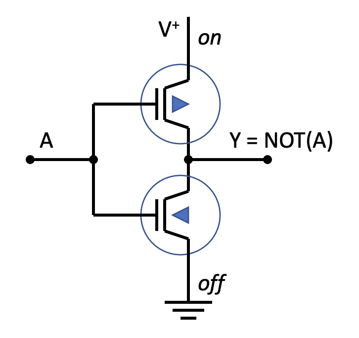
Building a NOT circuit
We need two switches to build a NOT:
- \(\texttt{V}^+\) is a constant source of high voltage
 is a ground connection (low voltage)
- A is the input wire
- Y is the output wire
- The triangles in the switches indicate
-
differing response to the gate input:
- when one is open,
- the other will be closed
The way it works is shown below:
From Notations for Boolean functions to Circuit Diagrams
There are three ways in which we can represent Boolean functions:
- A Truth Table (which shows inputs and outputs for a function);
- Algebraic notation: Mathematical description of the combination of operators and symbols that make the funciton;
- Physical (real or simulated) Circuit Diagram
We've seen the first two, now let's see how we can create a circuit diagram that replicates the behavior indicated by a truth table or a mathematical notation.
Circuit Diagrams
Let's now look at converting the truth tables and algebraic notations into actual circuits!
We will be using the simplified circuit symbols that represent each gate.
Working Backwards
Before building complex circuits, let's analyze one (break it into parts and understand its function).
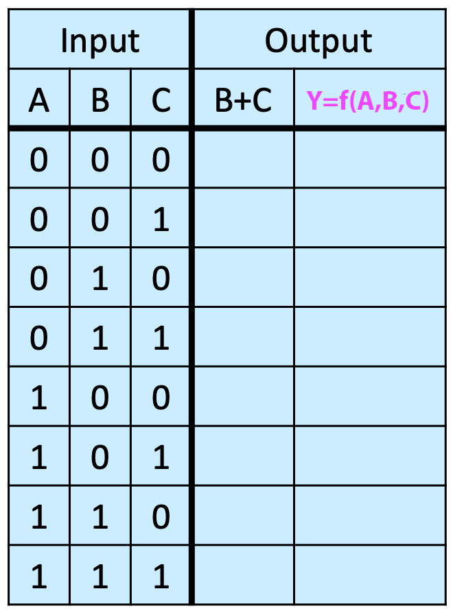
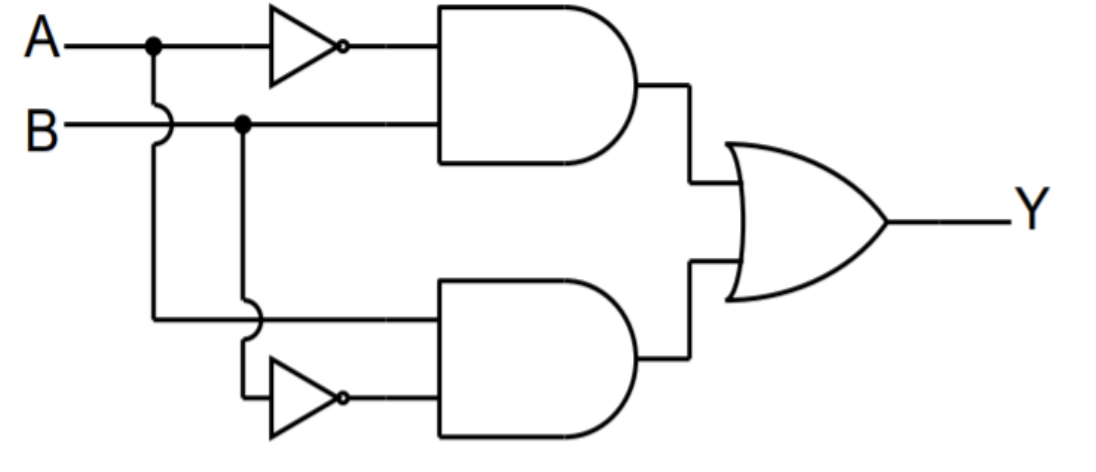
Activity 3 :[2 minutes] : Analyze this diagram and discover the behavior of the circuit:
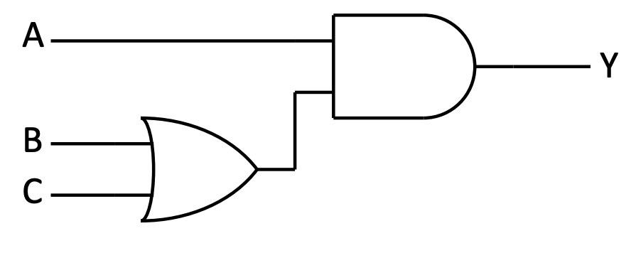
Express the output (
Y) in terms of the inputs (
A,
B,
C).
- Express this circuit in algebraic notation.
-
Fill out the following table:
Working Forwards
We're going to produce two circuits using an online simulator.
The link for the simulator is this one:
logic.ly
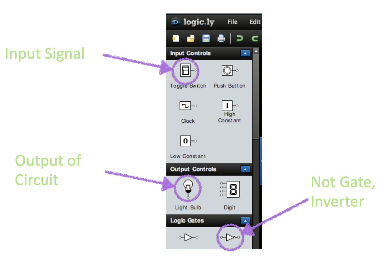
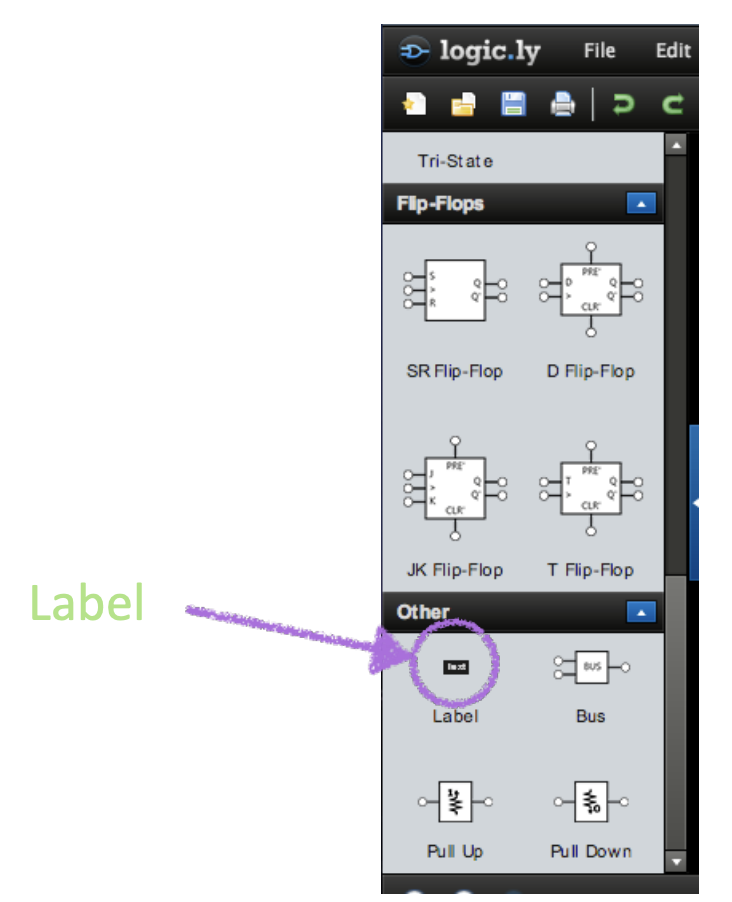
The following image shows the main view of the work area:
(No need to buy it!)
The following are the symbols for "input", "lightbulb output", and a "NOT" gate.
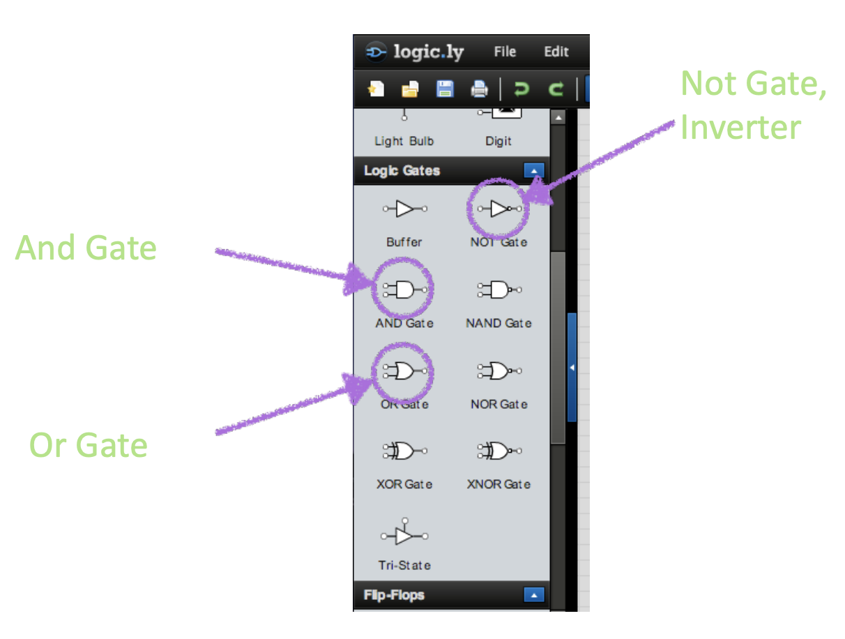
The following are the symbols for "and", an "or", and "NOT" gates.
The following is the "label" sign (to mark or annotate your circuits).
You can see several examples here:
logic.ly samples.
Circuit Exercises
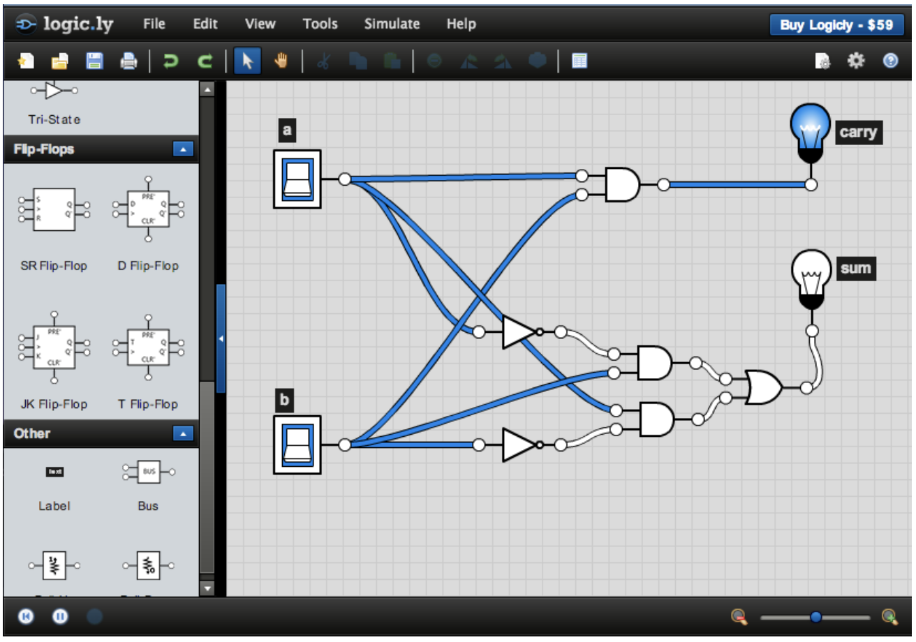
Activity 4 :[3 minutes] : Use the simulator to replicate this circuit and extract its truth table or algebraic expression:
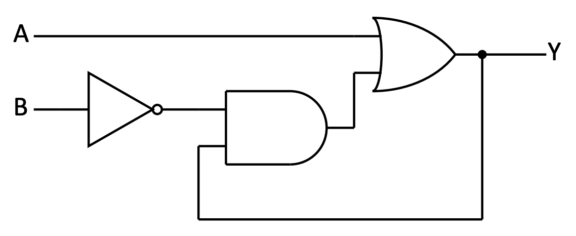
You'll note that the output is "fed-back" to the input. That is OK. Simply build the circuit to test how it works and follow the rules to build a table.
- First: How many inputs does this have?
- Second: Build the algebraic notation and/or truth table (you can use the actual circuit to verify)
- Third: Are all input-output combinations possible?
Activity 5 :[3 minutes] : Use the simulator to construct the circuit for the following expression:
\[ Y=( \overline{A \cdot B} ) \oplus (C+D) \]
If we have time:
Activity 6 :[3 minutes] : Create the diagram and truth table for the following circuit:
Note that:

The Format for the Final Project
The final project will have the following format:
- Teams of two or three
- Each team will chose a topic (see below)
- You will write a 3-4 page essay (1000 - 1500 words)
- You will prepare an oral presentation (which we might convert to a video presentation if needed)
- You will focus on a specific aspect of computer technology and:
- Explain how it works
- Discuss the current "state of the art" for this technology
- Where might any advances (based on current research) take this technology
- Discuss possible consequences for society (good/bad) from the advancement of this technology
- [OPTIONAL] You may include a 1-page short story based on this technology (I am partial to Sci-fi, horror, mystery, and comedy).
Topics:
- Multi-core processors
- Smartphone
- Tablet
- Parallel computing
- Sensor technology
- Chatbots
- Cloud gaming
- Smart speakers (Alexa, Siri, Cortana)
- Computing in the medical world (bioinformatics, biomedical informatics)
- Speech recognition technology and software
- Wearable computing
- Sensor technology
- Nanotechnology and computing
- Supercomputers
- Quantum computers
- Robotics
Before next class (Thursday 09/16)
[Due for everyone]
- Submit Homework 1 in Moodle before Wednesday 09/15 at 11:59
- Start making teams and choosing topics
read about
Signed number representation
1-Minute Debrief
Please fill this out before leaving: